Force properties and compliant properties on musculoskeletal robot
“Maximum output force profile” and compliant properties as a framework to design a musculoskeletal robot.
Overview
A musculoskeletal robot can benefit from pneumatic artificial muscles to execute dynamic motions. A dynamic motion is characterized by large instantaneous force and short duration. Therefore, force properties become important to design a musculoskeletal robot.
“Maximum output force profile” (MOFP) is explained here to describe the force properties of a musculoskeletal system. MOFP represents the maximum output force vectors distribution on the end-effector. MOFP can also be used to analyze the joint compliances.
This note mainly explains the proposed MOFP from reference [2].
Maximum Output Force Profile
Based on a geometric method, the force properties of a two-link musculoskeletal arm can be defined as a polygonal force distribution [1]. More generally, a “Maximum output force profile” was introduced to define the force properties for a musculoskeletal system with more than two joints [2].
Muscle output force distribution
The mechanism of a two-joint link mechanism with two motors (placed directly on each joint) and a two-joint link mechanism with muscles are greatly different [1]. The figure below shows the difference in the output force distribution from the individual actuator.
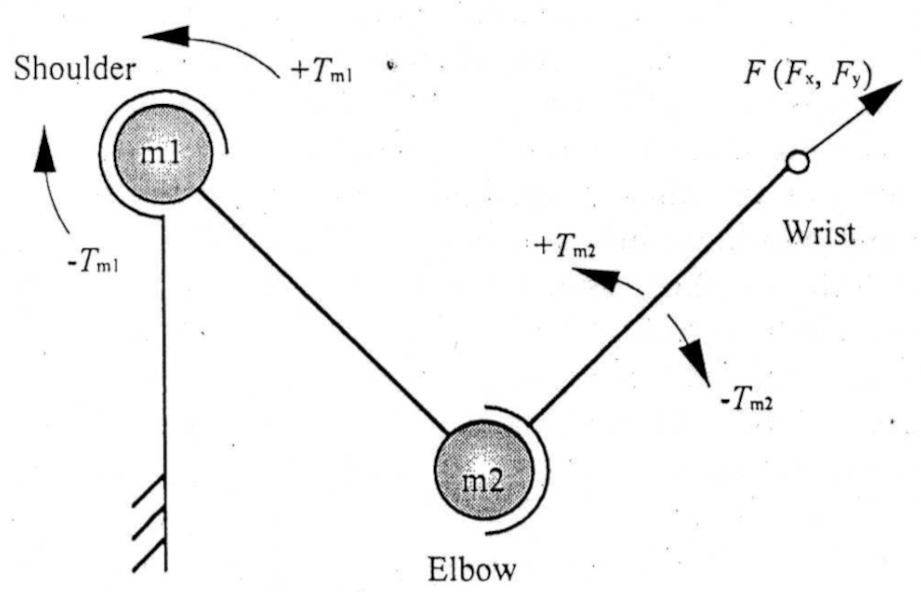
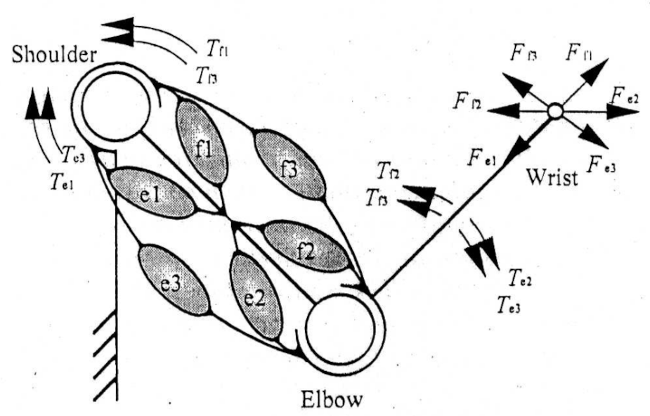
Fig.1 Two-joint mechanism with two motors (left) and six muscles (right) [1]
The output forces distribution developed by multiple muscles system in any direction could be derived by geometrical summation of the individual force vectors [1]. The output force distribution is in a polygonal shape. From the figure below, the output force distribution is defined with the hexagon denoted by point A~F.
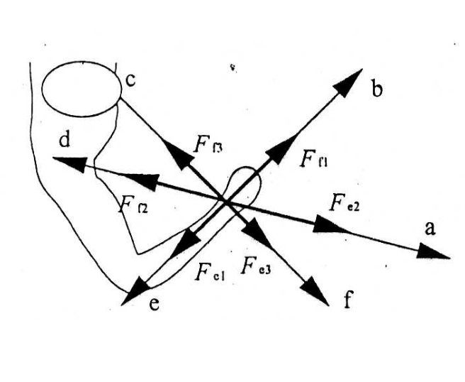
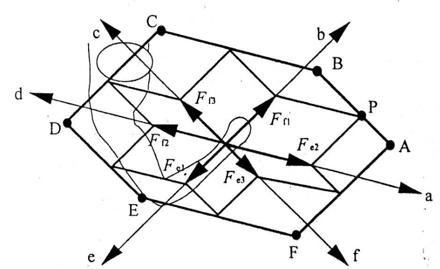
Fig.2 Individual output forces by muscles (left) and output force distribution (right) [1]
Concept of maximum output force profile

Fig.3 Concept of MOFP [2]
“Maximum output force profile” (MOFP) is introduced to describe the force properties of a musculoskeletal system [2]. The method is applicable for a system with more than two joints. Based on the muscle output force distribution [1], the musculoskeletal system is represented by a serial-link structure.
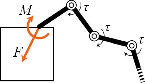
Fig.4 Statics of serial-link structure [2]
On a serial-link structure, consider the Jacobian matrix \(\mathbf{J} = \frac{\partial \mathbf{x}}{\partial \mathbf{q}}\) which represents the differential relationship between the joint motion \(\dot{\mathbf{q}}\) and the end-effector motion \(\dot{\mathbf{x}}\).
The free-body diagram for the serial-link structure is shown in Fig.4. Let \(\mathbf{Q}\) be the endpoint force and moment vector, consisting of forces \(\mathbf{F}\) and moments \(\mathbf{M}\) that the end-effector applies to the environment.
\[\mathbf{Q} = \begin{bmatrix} \mathbf{F} \\ \mathbf{M} \end{bmatrix}\]Because of the duality of differential kinematics and statics [3], the equivalent joint torques are related to the endpoint force by the Jacobian matrix. Therefore, the joint torque vector \(\tau\) is:
\[\tau = {\mathbf{J}}^T \mathbf{Q}\]From the musculoskeletal system approach [4], consider another Jacobian matrix \(\mathbf{G}\) which represents the relationship between the joint motion and the muscle (actuator) motion. Similarly, we can get the joint torque vector as:
\[\tau = {\mathbf{G}}^T \mathbf{f}\]with \(\mathbf{f}\) denotes the output force of the muscles. The Jacobian matrix \(\mathbf{G}\) consists of the moment arms of the muscles for each joint.
Force profile of a 3-DoF musculoskeletal leg
Consider a musculoskeletal leg that moves only in the sagittal plane as shown in the figure below.
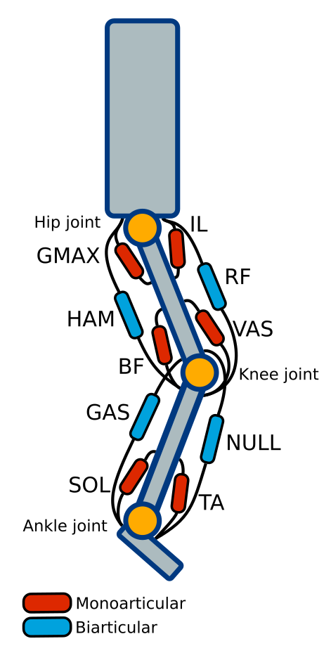
Fig.5 A musculoskeletal leg with muscles working only in the sagittal plane
By involving both monoarticular and biarticular muscles, the muscles actuating the three joints (hip, knee, ankle joints) are:
Table.1 Muscle configuration on 3-DoF musculoskeletal leg
| Symbols | Muscle name | Function |
|---|---|---|
| GMAX | Gluteus Maximus | Hip extensor |
| IL | Iliopsoas (Iliacus & Psoas Major) | Hip flexor |
| HAM | Hamstrings | Hip extensor + Knee flexor |
| RF | Rectus Femoris | Hip flexor + Knee extensor |
| BF | short head of Biceps Femoris | Knee flexor |
| VAS | Vastus | Knee extensor |
| GAS | Gastrocnemius | Knee flexor + Ankle extensor |
| NULL | Muscles that do not exist in human | Knee extensor + Ankle flexor |
| SOL | Soleus | Ankle extensor |
| TA | Tibialis Anterior | Ankle flexor |
The output force vector \(\mathbf{f}\) of the muscles is:
\[\mathbf{f} = {\begin{bmatrix} f_{G} & f_{IL} & f_{HAM} & f_{RF} & f_{BF} & f_{VAS} & f_{GAS} & f_{NULL} & f_{SOL} & f_{TA} \end{bmatrix}}^T\]The matrix \(\mathbf{G}\) has values based on each muscle function on each joint. Since flexor and extensor are opposite to each other, they decide the sign for the values in the matrix \(\mathbf{G}\). Note that we assign hip flexion, knee extension, and ankle flexion as the positive direction of the joints.
Based on Table.1, the matrix \(\mathbf{G}\) has unit values:
\[\mathbf{G} = {\begin{bmatrix} -1 & 1 & -1 & 1 & 0 & 0 & 0 & 0 & 0 & 0 \\ 0 & 0 & -1 & 1 & -1 & 1 & -1 & 1 & 0 & 0 \\ 0 & 0 & 0 & 0 & 0 & 0 & -1 & 1 & -1 & 1 \end{bmatrix}}^T\]Note that the rows are the muscles and the columns are the joints.
Using the joint torque vector equations, we can get the endpoint force and moment vector \(\mathbf{Q}\) as
\[{\mathbf{J}}^T \mathbf{Q} = {\mathbf{G}}^T \mathbf{f}\] \[\mathbf{Q} = ({\mathbf{J}}^T)^{-1} {\mathbf{G}}^T \mathbf{f}\]In the case of a legged robot, we cannot be obtained sufficient torque (moment of force) at the contact point [2], so \(\mathbf{Q} = \mathbf{F}\). Finally, we can define the polygonal shape of MOFP from the force vector \(\mathbf{F}\).
Example: Analysis of MOFP on various muscle configurations
The following examples are reproduction of the experiment results on [2].
Different muscle configurations affect the MOFP. To simplify, let the values of output force vector \(\mathbf{f}\) be 1 N for all muscles. We will define the MOFP for multiple configurations:
-
uniform: isotropic force profile for all muscles
\[\mathbf{G}_{uniform} = {\begin{bmatrix} -1 & 1 & -1 & 1 & 0 & 0 & 0 & 0 & 0 & 0 \\ 0 & 0 & -1 & 1 & -1 & 1 & -1 & 1 & 0 & 0 \\ 0 & 0 & 0 & 0 & 0 & 0 & -1 & 1 & -1 & 1 \end{bmatrix}}^T\] -
anthropomorphic: human-like muscle configuration
\[\mathbf{G}_{anthropomorphic} = {\begin{bmatrix} -2 & 2 & -0.5 & 0.5 & 0 & 0 & 0 & 0 & 0 & 0 \\ 0 & 0 & -0.5 & 0.5 & 0 & 2 & -0.5 & 0 & 0 & 0 \\ 0 & 0 & 0 & 0 & 0 & 0 & -0.5 & 0 & -2 & 0.5 \end{bmatrix}}^T\] -
symmetric monoarticular: similar joint mechanism with electric motors with no biarticular muscle
\[\mathbf{G}_{monoarticular} = {\begin{bmatrix} -2 & 2 & 0 & 0 & 0 & 0 & 0 & 0 & 0 & 0 \\ 0 & 0 & 0 & 0 & -2 & 2 & 0 & 0 & 0 & 0 \\ 0 & 0 & 0 & 0 & 0 & 0 & 0 & 0 & -1 & 1 \end{bmatrix}}^T\]
With the joint angles \(\mathbf{q} = {\begin{bmatrix} \frac{\pi}{6} & -\frac{\pi}{2} & \frac{2\pi}{3} \end{bmatrix}}^T\), the MOFP for each configuration are shown as below.
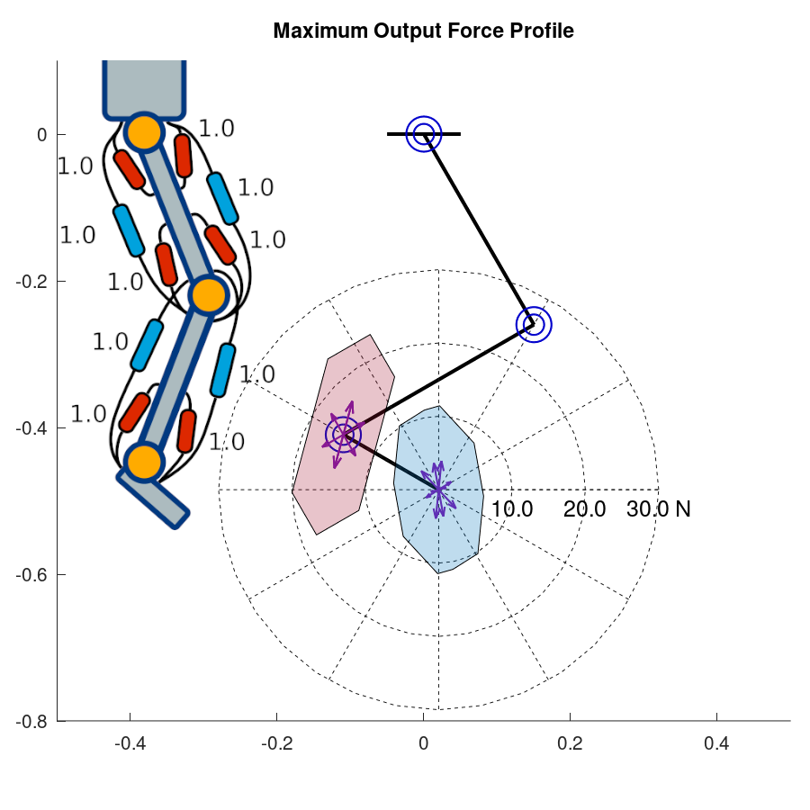
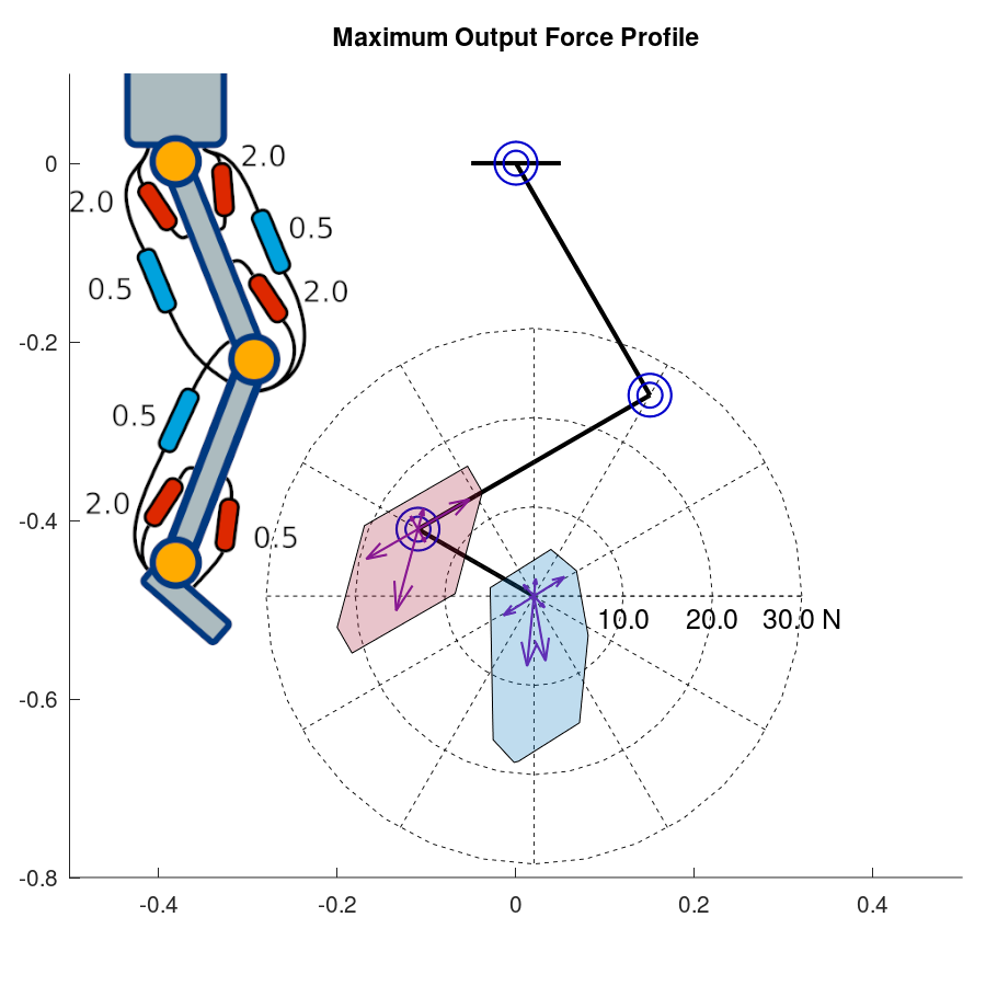
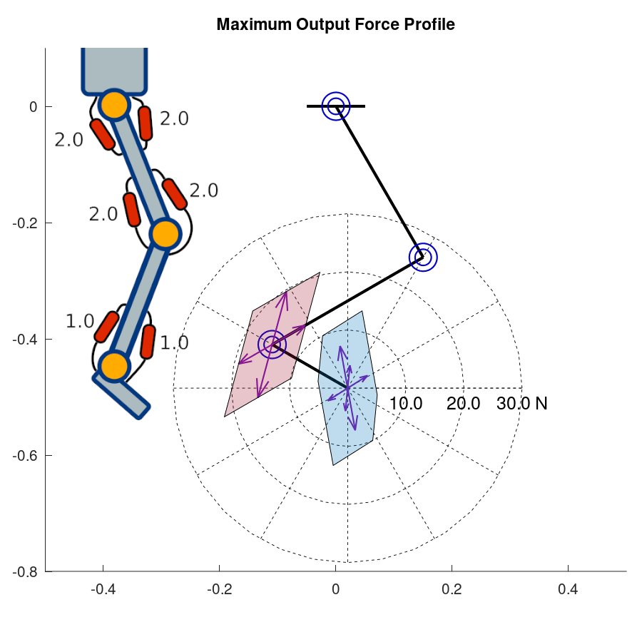
Fig.6 (a) Uniform , (b) anthropomorphic, (c) symmetric monoarticular configurations
From this example, we can create a design framework for the muscle configuration of a musculoskeletal robot based on the target maximum output force profile.
Angle-Dependent Moment Arm
From the previous section, the Jacobian matrix \(\mathbf{G}\) consists of the moment arms of the muscles for each joint. On the example, we used constant moment arms for each muscle. However, to improve the physical abilities of robots in dynamic motions, the torque-angle relation of the muscles need to be modified [5]. Instead of using a constant moment arm, Angle-Dependent Moment Arm (ADMA) was proposed [5].
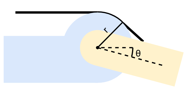
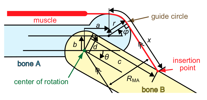
Fig.7 Constant moment arm (left) and Angle-Dependent Moment Arm [5] (right) mechanism
On a muscle mechanism with constant moment arm, a guide circle is placed at the origin of the joint. Note that a guide circle is needed to implement a muscle actuator on a joint.
On ADMA mechanism, we applied translation to the guide circle to create an angle-dependent moment arm (ADMA). For moment arm calculation on a joint \(i\) (that rotates link \(i\)+1), ADMA requires constant parameters:
- \(a\), translation parallel to link \(i\)
- \(b\), translation perpendicular to link \(i\)
- \(c\), position of insertion point from the center of rotation, parallel to link \(i\)+1
- \(d\), position of insertion point from the center of rotation, perpendicular to link \(i\)+1
- \(r\), radius of the guide circle
and the joint angle \(\theta\).
Moment Arm \(R\)
To make it easier to understand how to calculate the ADMA, refer to the following figure.
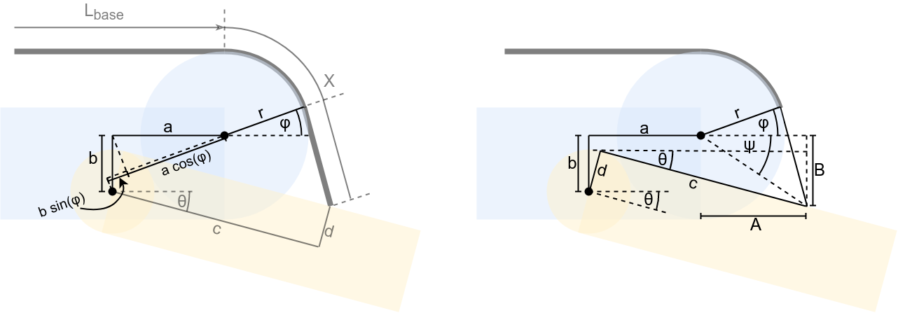
Fig.8 Angle-Dependent Moment Arm calculation reference
The moment arm \(R\) is:
\[R = r + a \cos\phi + b \sin\phi\]To get \(\phi\), we can have additional variables \(A\), \(B\), and \(C=\sqrt{A^2+B^2}\), so
\[\phi+\psi = \cos^{-1} (\frac{r}{C}) = \cos^{-1} (\frac{r}{\sqrt{A^2+B^2}})\] \[\phi = \cos^{-1} (\frac{r}{\sqrt{A^2+B^2}}) - \tan^{-1} (\frac{A}{B})\]With \(A = -a + c \cos\theta + d \sin\theta\) and \(B = b + c \sin\theta - d \cos\theta\).
Wire length \(X\)
Since the muscle length is important to calculate the muscle output force, we can also calculate the wire length on ADMA mechanism. From Fig.7 and Fig.8, \(X\) is the wire length from the guide circle to the insertion point. Note that for a pneumatic artifical muscle, \(X\) will only be the wire, not the muscle.
For the calculation we can divide \(X\) into two parts: wire around the guide circle \(X_{guide circle} = (\frac{\pi}{2} + \phi) r\), and wire perpendicular to the guide circle \(X_0\):
\[X_0 = \begin{cases} \frac{A - r \cos\phi}{\sin\phi}, & \text{if}\ \phi=\frac{pi}{2}\ \text{or}\ \phi=\frac{-pi}{2} \\ \frac{B + r \sin\phi}{\cos\phi}, & \text{otherwise} \end{cases}\]So, we can have the wire length
\[X = X_0 + (\frac{\pi}{2} + \phi) r\]Updates:
- (Dec 2021) The scripts to run MOFP analysis on a musculoskeletal leg is available at musculoskeletal-MOFP repo (running in Octave).
References:
[1] T. Oshima, T. Fujikawa, O. Kameyama, and M. Kumamoto, “Robotic analyses of output force distribution developed by human limbs” Proceedings 9th IEEE International Workshop on Robot and Human Interactive Communication, pp. 229-234, 2000.
[2] R. Niiyama and Y. Kuniyoshi, “Design principle based on maximum output force profile for a musculoskeletal robot”. Industrial Robot: An International Journal, 2010.
[4] K. Ito, T. Tsuji, and M. Nagamachi. “Motor impedance and inverse kinematics in musculoskeletal systems” Proceedings of the Annual International Conference of the IEEE Engineering in Medicine and Biology Society, pp. 635-636, 1988.
[5] S. Nishikawa, K. Tanaka, K. Shida, T. Fukushima, R. Niiyama, Y. Kuniyoshi, “A musculoskeletal bipedal robot designed with angle-dependent moment arm for dynamic motion from multiple states” Advanced Robotics, vol. 28, no. 7, pp. 487-496, 2014.