Forward Kinematics
Notes on forward kinematics to get joint positions from joint angles.
Introduction
Forward kinematics computes the joint positions from the joint angles.
Example: 2D serial link robot

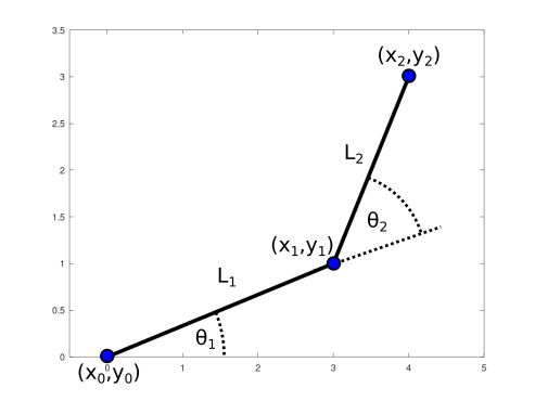
A planar 2-DOF serial link robot
Consider a planar (in simple 2D Cartesian space) robot with two serial link robot as shown above.
By applying simple trigonometry, we can get the position for each joint as:
\[x_1 = L_1 cos(\theta_1)\] \[y_1 = L_1 sin(\theta_1)\] \[x_2 = L_1 cos(\theta_1) + L_2 cos(\theta_1 + \theta_2)\] \[y_2 = L_1 sin(\theta_1) + L_2 sin(\theta_1 + \theta_2)\]Forward kinematics let us to formulate the relation between the joint angle \(\theta\) and the joint position \(\textbf{x} = \begin{bmatrix} x \\ y \end{bmatrix}\)
Robot Configuration
First, let us define the robot configuration to make it easier to understand the terms used on the following sections.

On an \(n\)R serial link robot, we have \(n\) joints \(joint_1,...,joint_n\) which move \(n\) links \(L_1,...,L_n\).
Each joint has an end-effector—maybe not a really good choice of word as it usually means for the last joint—
\(\textbf{x}_i = {\begin{bmatrix} x_i & y_i\end{bmatrix}}^T\).
From the above picture, joint 1 has an end-effector located at \(x_1\) and \(y_1\). Also note that \(joint_i\) is placed on \(x_{i-1}\) and \(y_{i-1}\)
Transformation Matrix
We will use transformation matrices to build the formula for the forward kinematics. Transformation matrix allows a given point to be transformed between different reference frames. Using this, we can transform the position of end-effector of link \(i\) from its reference frame \(i\) to the reference frame \(i\)-1.
We will divide the transformation matrix to rotation matrix and translation matrix first.
Rotation Matrix
A rotation matrix are straight-forward to define as
\[R_{i}^{i-1} = \begin{bmatrix} cos(\theta_i) & -sin(\theta_i) \\ sin(\theta_i) & cos(\theta_i) \end{bmatrix}\]with \(R_{i}^{i-1}\) denotes the rotation from reference frame \(i\) to reference frame \(i\)-1 with an angle \(\theta_i\) with respect to the \(x\) axis of reference frame \(i\)-1 (counterclockwise).
Translation Matrix
A translation matrix are straight-forward to define as
\[D_{i}^{i-1} = \begin{bmatrix} x \\ y \end{bmatrix}\]with \(D_{i}^{i-1}\) denotes the translation from reference frame \(i\) to reference frame \(i\)-1.
With the serial link robot example, the reference frame of joint \(i\) is placed \(L_{i-1}\) away from the joint \(i\)-1.
So, the translation matrix for the serial link robot is defined as
Transformation Matrix from Rotation and Translation Matrices
From rotation and translation matrices, the transformation matrix is defined as
\[T_{i}^{i-1} = \begin{bmatrix} R_{i}^{i-1} & D_{i}^{i-1} \\ 0 & 1 \end{bmatrix} = \begin{bmatrix} cos(\theta_i) & -sin(\theta_i) & L_{i-1}\\ sin(\theta_i) & cos(\theta_i) & 0\\ 0 & 0 & 1 \end{bmatrix}\]For an \(n\)R serial robot, we can have tranformation matrix for each joint \(n\) to the base reference frame (say reference frame 0) as
\[T_n = T_n^0 = \prod_{i=0}^n T_{i}^{i-1} = T_{1}^{0} T_{2}^{1} ... T_{n}^{n-1}\](Note: we use \(n\) here just to differentiate with iterator \(i\))
Joint Position and End-effector Position from Transformation Matrix
We can calculate the joint position and the end-effector position from the transformation matrix.
Note that joint \(i\) is placed at the end-effector position of joint \(i\)-1.
Any end-effector of joint \(i\) is placed \(L_i\) away from the origin of joint \(i\). Therefore, the position of the end-effector is
\[\textbf{x}^i = \begin{bmatrix} L_{i} \\ 0 \\ 1 \end{bmatrix}\](Note: 1 is added to make a 3x1 matrix. \(\textbf{x}^i\) denotes the position in reference frame \(i\))
The end-effector of each joint \(i\) in the reference frame 0 is defined as
\[\textbf{x}_i^0 = T_i \textbf{x}^i\]Canonical example: 2R robot
Using transformation matrices, we can get the end-effector position for the 2R serial robot.
The transformation matrices are
\[T_1 = \begin{bmatrix} cos(\theta_1) & -sin(\theta_1) & L_0\\ sin(\theta_1) & cos(\theta_1) & 0\\ 0 & 0 & 1 \end{bmatrix}\] \[T_2 = T_1^0 T_2^1 = T_1^0 \begin{bmatrix} cos(\theta_2) & -sin(\theta_2) & L_1\\ sin(\theta_2) & cos(\theta_2) & 0\\ 0 & 0 & 1 \end{bmatrix} = \begin{bmatrix} c_{12} & -s_{12} & L_0 + L_1 c_1 + L_2 c_{12} \\ s_{12} & c_{12} & L_1 s_1 + L_2 s_{12} \\ 0 & 0 & 1 \end{bmatrix}\]with \(c_{1} = cos(\theta_1)\), \(s_{1} = sin(\theta_1)\), \(c_{12} = cos(\theta_1+\theta_2)\), \(s_{12} = sin(\theta_1+\theta_2)\).
Then, the end-effector of each joint \(i\) are
\[\textbf{x}_1^0 = T_1 \textbf{x}^1 = T_1 \begin{bmatrix} L_1 \\ 0 \\ 1 \end{bmatrix} = \begin{bmatrix} L_0 + L_1 c_1 \\ L_1 s_1 \\ 1 \end{bmatrix}\] \[\textbf{x}_2^0 = T_2 \textbf{x}^2 = T_2 \begin{bmatrix} L_2 \\ 0 \\ 1 \end{bmatrix} = \begin{bmatrix} L_0 + L_1 c_1 + L_2 c_{12} \\ L_1 s_1 + L_2 s_{12} \\ 1 \end{bmatrix}\]With \(L_0 = 0\), the results are consistent with the result on introduction section.